

A CNC press brake is a force machine with a controlled geometry. A punch is mounted on a moving ram, a die sits in the bed below it, and a flat blank is placed between them. The ram comes down, the blank is forced into the die opening, and a bend is left where the material was pushed past its yield point. The CNC system’s job is to put the ram at the same depth and the blank at the same position every time, so that the bend comes out the same on the last part as on the first.
That description is deliberately plain, because most of what goes wrong with press brakes is not a control problem. It is a misunderstanding of what the machine is being asked to do to the material.
Folding a steel plate is three different processes, and the machine is set for one of them.
Air bending presses the punch into the die opening without the material touching the bottom of the die. The angle is set by how far the ram travels, so one toolset can produce a range of angles, and the force required is the lowest of the three. The trade is that the angle depends on the material, because every material springs back differently, and the machine has to over-bend to land on the target angle.
Bottoming drives the material until it touches the die walls, with the punch radius forming the inside of the bend. The angle is set by the tooling rather than by the ram depth, so it repeats more reliably, and it needs more force.
Coining presses the material hard enough that the punch tip penetrates the thickness and the die walls are filled. The angle is formed by the tooling and is the most consistent of the three, and the force required is the highest by a wide margin — high enough that coining is a decision about the machine’s tonnage rather than about the part.
Which of these the shop intends to use decides the machine, the tooling and the tonnage. A buyer who specifies a press brake by “the thickest plate we bend” without saying which process will be used is specifying a machine that may be right for one and inadequate for another.
The force is not one number, and the plate’s thickness is not the only input.
The tonnage a bend requires rises with the length of the bend, with the strength of the material, and steeply with the thickness — thickness enters the calculation far more heavily than length does, which is why a machine that handles a long thin sheet comfortably can be defeated by a short thick one.
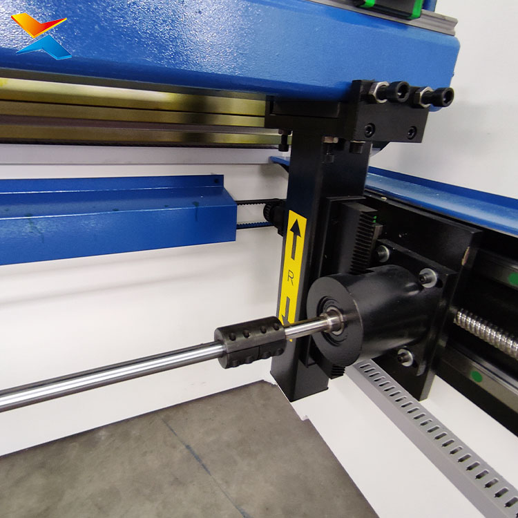
The die opening is the other half of the calculation. A wider opening needs less force and produces a larger inside radius; a narrower opening needs more force, gives a tighter radius and risks marking the outside of the bend. The inside radius of a bend is set by the die opening rather than by the punch tip, which is the single most common misconception in press brake buying: a sharper punch does not make a tighter bend if the die is wide.
Which is why a press brake’s capacity cannot be read off a single figure. The same machine has one capacity for a short bend in mild steel and a much smaller one for a long bend in a stronger material, and the tooling in the bed changes both. A capacity table that gives one tonnage and one thickness is a table for one combination, not for the machine.
Springback is the material’s answer to being bent, and the control is the machine’s answer to springback.
Every material returns part of the bend when the ram lifts. Mild steel returns a little; stainless and high-strength steels return a great deal more, and a bend that was correct in the trial will be wrong when the material changes.
A CNC system deals with this by bending past the target angle and letting the material come back to it. The amount of over-bend is either set from experience or measured — some systems measure the achieved angle and correct the ram depth for the next part. What the control cannot do is know a material it has not been told about: a new coil, a different grade, a different supplier’s steel is a different springback, and the first part of a new batch is a trial whether the machine is CNC or not.
The hardest bend on a long part is the one in the middle.
Under load, the ram and the bed deflect. The deflection is greatest at the centre of the machine and zero at the ends, so a long bend made without compensation is deeper at the two ends and shallower in the middle — a part that measures correct at both ends and is out of tolerance at the middle.
This is what crowning is for. The bed is built with a curve, or adjusted mechanically or hydraulically, so that the deflection under load is cancelled. It is the reason a long press brake is a different machine from a short one rather than a stretched version of it, and it is the reason a shop that bends long parts should be asking about crowning before it asks about the control.
A part that is correct at both ends and wrong in the middle cannot be fixed by re-programming the angle. The angle is right; the machine is bowing.
What the control actually buys, and what it does not.
It buys repeatability, not automation. A CNC press brake stores the ram depth, the back gauge position and the sequence for a part, so the same part can be made again next month by a different operator and come out the same. On a shop that makes a few hundred different brackets, frames and profiles, that is the whole value: the knowledge lives in the program instead of in one man’s hands.
It buys setup time. Changing from one part to another is a program change and a gauge move rather than a series of trial bends, which is what makes short runs economic.
It does not buy a correct part from a wrong blank. The machine bends what it is given, along the line where the gauge holds it. The length of the blank is calculated from the bend allowance before anything is cut — the flat pattern that a fabricator cuts on the laser or the shear has to carry the correct allowance for each bend, and a blank that is short will produce a part that is short in every direction no matter how accurate the bend angle is. A press brake can hold an angle to a fine tolerance and still deliver a part that does not fit, because the error was made at the nesting stage.
It does not set the bend line. The back gauge positions the blank, and the gauge position defines where the bend lands. A part with several bends is a sequence in which each bend is measured from a previous one, and the accumulated error grows with the number of bends — which is why the order of bending is part of the program and not a matter of operator preference.
Tooling is a separate decision from the machine, and it limits what the machine can make.
A punch and a die are a matched pair. The punch’s tip radius and angle, the die’s opening and its V angle, and the material’s thickness together decide the bend. Buying a machine with one general-purpose toolset and expecting it to make every part is the most common way a new press brake disappoints its owner.
Segmented tooling is what makes boxes and return flanges possible. A one-piece punch cannot bend a part that has already been folded up on both sides — the flanges would hit the tooling. Segmented punches and dies let the tooling be assembled around the part, and the width of the segments is what sets the minimum inside clearance the machine can work in.
Tooling also sets the marking. A sharp die edge marks the outside of a bend on coated or polished material. Where the part will be seen, the tooling choice matters as much as the machine’s accuracy — and on stainless or aluminium work, protective film and a larger die opening are the difference between a delivered part and a rejected one.
What the machine does not do.
It does not cut. A press brake forms bends in a blank that has already been cut to shape. A shop that needs shearing, laser cutting or punching is buying those as separate machines, or buying a machine that combines them.
It does not make long uniform profiles. A press brake makes discrete bends one at a time along a part. A roof sheet, a purlin, a decking panel or a cladding profile is made by roll forming, continuously, in one pass — a press brake cannot substitute for that, and a roll former cannot substitute for a press brake. The two are different answers to different questions and a fabrication shop usually needs both, in that order.
It does not remove the operator. A CNC press brake reduces the skill needed to repeat a part; it does not remove the judgement needed to hold a long part, to turn a heavy blank, or to decide that a bend sequence will not work before the tooling is set up. The machine’s guards and its control assume an operator is present, and on a press brake that is where the safety design is concentrated.
Safety is part of the specification, not an accessory.
A press brake is the machine in a fabrication shop where hands are closest to the tooling. The guard arrangement is what stands between an operator and a closing tool, and it has to be in place before the machine is commissioned — not ordered after the first near miss.
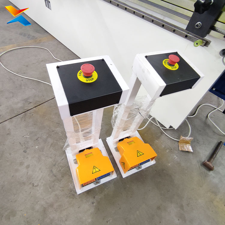
Light curtains and laser guards protect the approach to the tooling by stopping the ram when the plane is broken, and they need to be positioned for the tooling that is actually fitted, because the protected zone changes with the punch and die. Two-hand control and a foot pedal are different risk profiles, and a shop that works with long parts held by two operators has a different requirement from one that bends small brackets alone.
A machine that arrives without its guarding resolved is not a finished machine, which is why the guarding arrangement belongs in the scope of supply rather than in a later conversation.
The Middle East conditions that act on a press brake.
Hydraulic oil temperature is the first one, and it is not a small one. A press brake in an unconditioned shop in this region works in ambient heat that keeps hydraulic oil hot through the whole shift. Oil that runs too hot loses viscosity, the valves respond less predictably, and the ram’s positioning becomes less consistent — which shows up as bends that drift through the day rather than as a machine that fails. An oil cooler is not a luxury on a machine in this climate; it is the difference between a machine that holds tolerance in the afternoon and one that does not.
Dust and grit on the machine’s measuring surfaces. The back gauge runs on guides, and some machines measure position on linear scales. Fine dust that settles on a scale or a guide is a positioning error that repeats, and a shop next to a yard or a cutting operation has more of it than the machine’s design assumes. Keeping the gauge area covered and clean is maintenance, and it is scheduled maintenance, not a response to a fault.
Coastal air and the machine’s own steel. A press brake is a heavy steel structure with machined surfaces, and in a coastal industrial area the unpainted and machined surfaces are what corrode first. The painted frame survives; the gauge rails, the tooling and the exposed ends do not, and tooling kept in a coastal shop needs protection between jobs.
Power. Industrial supply in the region varies between sites, and the machine is built for one voltage, frequency and phase. This is settled at order and cannot be corrected by a setting afterwards. A three-phase supply of the right configuration, sized for the machine’s motor, is a site requirement — and a shop that intends to run the machine off a generator should say so before the machine is built, because the supply characteristics change the electrical specification.
The fabrication work this machine is bought for here.
Structural and miscellaneous steel — base plates, stiffeners, connection brackets, folded sections for mezzanines and canopies. Trailer and vehicle body building — folded panels and channels in sheet that has to be consistent from unit to unit. Signage and architectural metalwork — folded fascias and cladding trims where the visible fold has to be clean. Sheet metal enclosures and equipment frames — repeated parts in short runs, which is where a stored program pays for itself. Light structural work in workshops serving the building trade, where a folded profile is quicker to make than to order.
What the machine needs from the building.
A floor that carries the machine and the blank. A press brake is heavy for its footprint, and a long machine concentrates that weight along its length. The floor has to be level, because a machine that is not level bends along a line that is not true, and the error appears at the ends of long parts.
Space at both ends. A long part has to be carried through the machine and out the other side, and the working length of the machine is not the space the part needs — a bent channel of full machine length needs room to be turned. This is the constraint that surprises shops fitting a press brake into an existing bay.
Headroom for the ram and for lifting tooling. Punches and dies are heavy, and they are lifted into the machine. Tooling storage near the machine, at a height a person can reach, is part of the layout rather than an afterthought.
What arrives, and what is separate.
The machine arrives as a frame with the ram, the hydraulic system, the control and the back gauge, with the guarding arrangement that was specified with it. Tooling is usually a separate selection — the punch and die are chosen for the work, and a machine ordered with one general set is a machine that will need more tooling as the work widens. Crowning, if it is required, is a build decision and is not something added later.
The machine is set against the work, not against a catalogue. The thickness and the grade of the material, the longest bend, the sharpest inside radius required, the height of the flanges, and the sequence of bends on the most complex part — these are what decide the tonnage, the tooling, the crowning and the control, and they are all known before the machine is ordered.
In one sentence: a CNC press brake is a machine that repeats a bend accurately — and the accuracy of the part depends on the die opening, the crowning, the blank allowance and the tooling as much as on the control.

♦ COMPANY PROFILE:
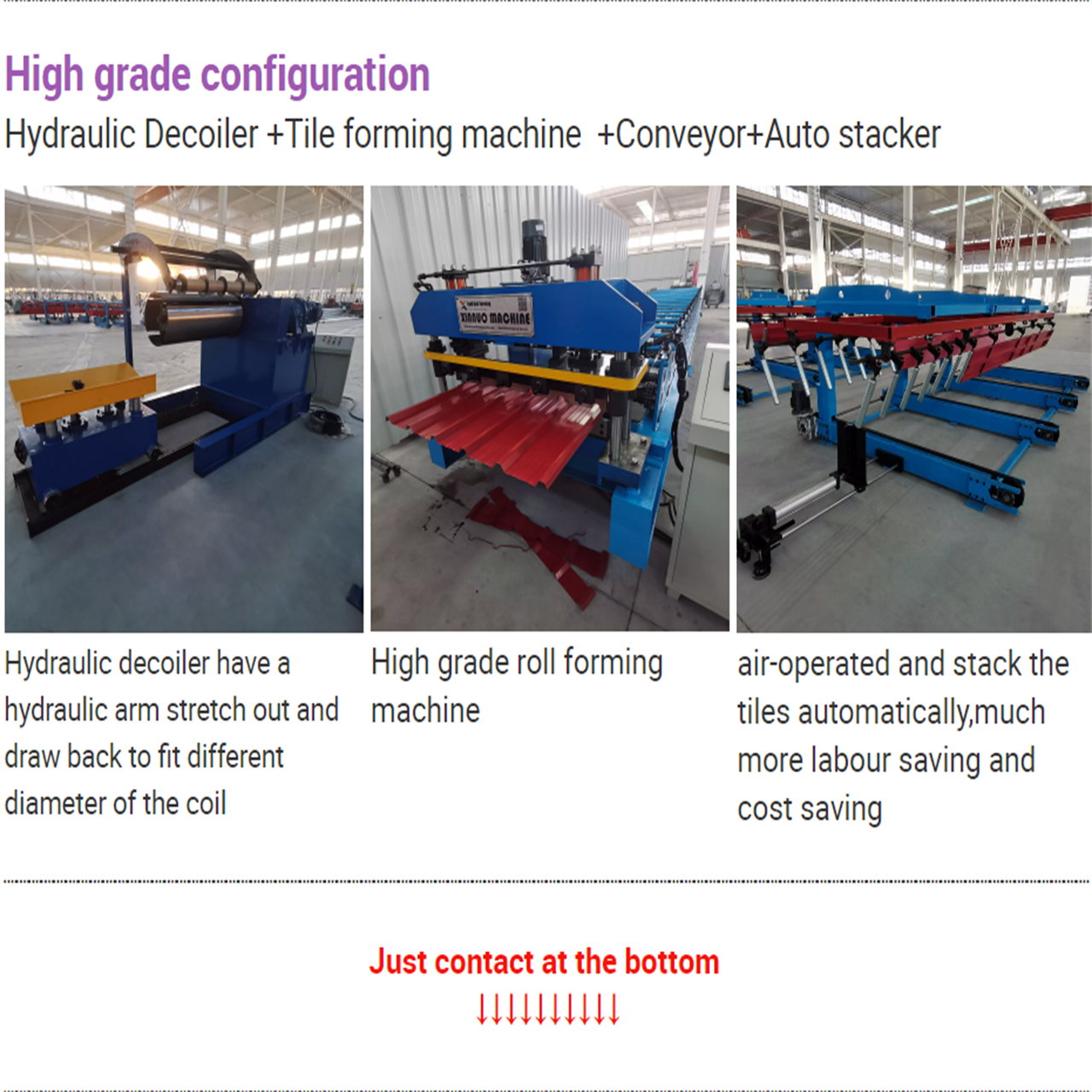
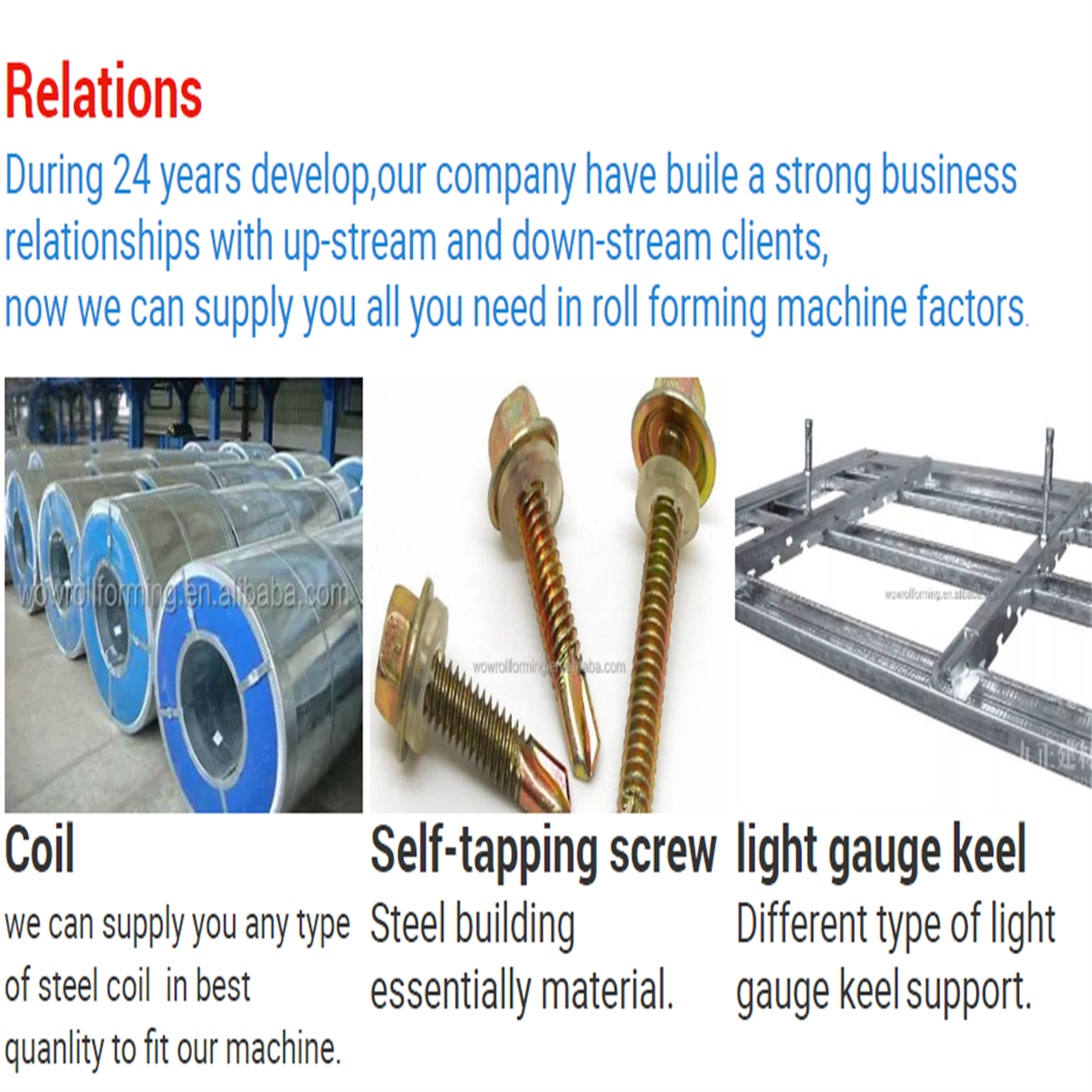
Hebei Xinnuo Roll Forming Machine Co., Ltd., not only produce different types of professional roll forming machines, but also develop intelligent automatic roll forming production lines, C&Z shape purline machines, highway guardrail roll forming machine lines, sandwich panel production lines, decking forming machines, light keel machines, shutter slat door forming machines, downpipe machines, gutter machines, etc.
There are several advantages of using roll forming for your projects:
- The roll forming process allows operations such as punching, notching, and welding to be performed in-line. Labor cost and time for secondary operations are reduced or eliminated, reducing part costs.
- Roll form tooling allows for a high degree of flexibility. A single set of roll form tools will make almost any length of the same cross-section. Multiple sets of tools for varying length parts are not required.
- It can provide better dimensional control than other competing metal forming processes.
- Repeatability is inherent in the process, allowing easier assembly of roll formed parts into your finished product, and minimizing problems due to “standard” tolerance build up.
- Roll forming is typically a higher speed process.
- Roll forming offers customers a superior surface finish. This makes roll forming an excellent option for decorative stainless steel parts or for parts requiring a finish such as anodizing or powder coating. Also, texture or pattern can be rolled into the surface during forming.
- Roll forming utilizes material more efficiently than other competing processes.
- Roll formed shapes can be developed with thinner walls than competing processes
In modern construction and manufacturing, the roll forming machine (commonly known as a roof tile or sheet metal roll former) has revolutionized profile fabrication. By replacing labor-intensive traditional press brake methods, advanced roll forming technology offers unmatched efficiency, quality, and cost savings for metal roofing and wall panel production.
Here are the key advantages of implementing a modern roll forming machine in your operations:
1. Unmatched High Efficiency and Output Speed
High-speed roll forming lines operate continuously, producing custom metal panels at speeds up to 20–40 meters per minute. This automated process significantly shortens lead times and accelerates project delivery cycles.
2. High Precision and Consistent Quality
Engineered with heavy-duty steel frames, high-precision roller dies, and PLC automated control systems, roll formers deliver pinpoint dimensional accuracy. Every panel exhibits uniform thickness, sharp profiles, and precise hole punching, ensuring seamless job-site installation.
3. Material Efficiency and Reduced Waste
Continuous roll forming minimizes scrap metal generation compared to conventional stamping. Precise coil feeding and automated hydraulic flying shears ensure optimal material utilization and reduced raw material costs.
4. Low Maintenance and Extended Durability
Constructed with heat-treated chrome-plated rollers and robust drive systems, industrial roll forming machines require minimal downtime while delivering a long service life under heavy daily operation.
Conclusion
Investing in a reliable roll forming machine boosts productivity, lowers labor costs, and guarantees consistent product quality—delivering maximum long-term return on investment (ROI) for metal fabrication businesses.
Metal roll forming is a continuous, automated metal fabrication process used to shape long strips of sheet metal (usually coiled steel or aluminum) into specific, uniform cross-sectional profiles.
Unlike traditional metal bending techniques like press braking—which shapes sheets batch by batch—roll forming operates as a continuous production line, making it one of the most efficient manufacturing methods for structural profiles, roofing panels, and automotive components.
How the Metal Roll Forming Process Works
The process passes coil stock through a series of consecutive roller dies to incrementally shape the metal into a finished cross-section:
-
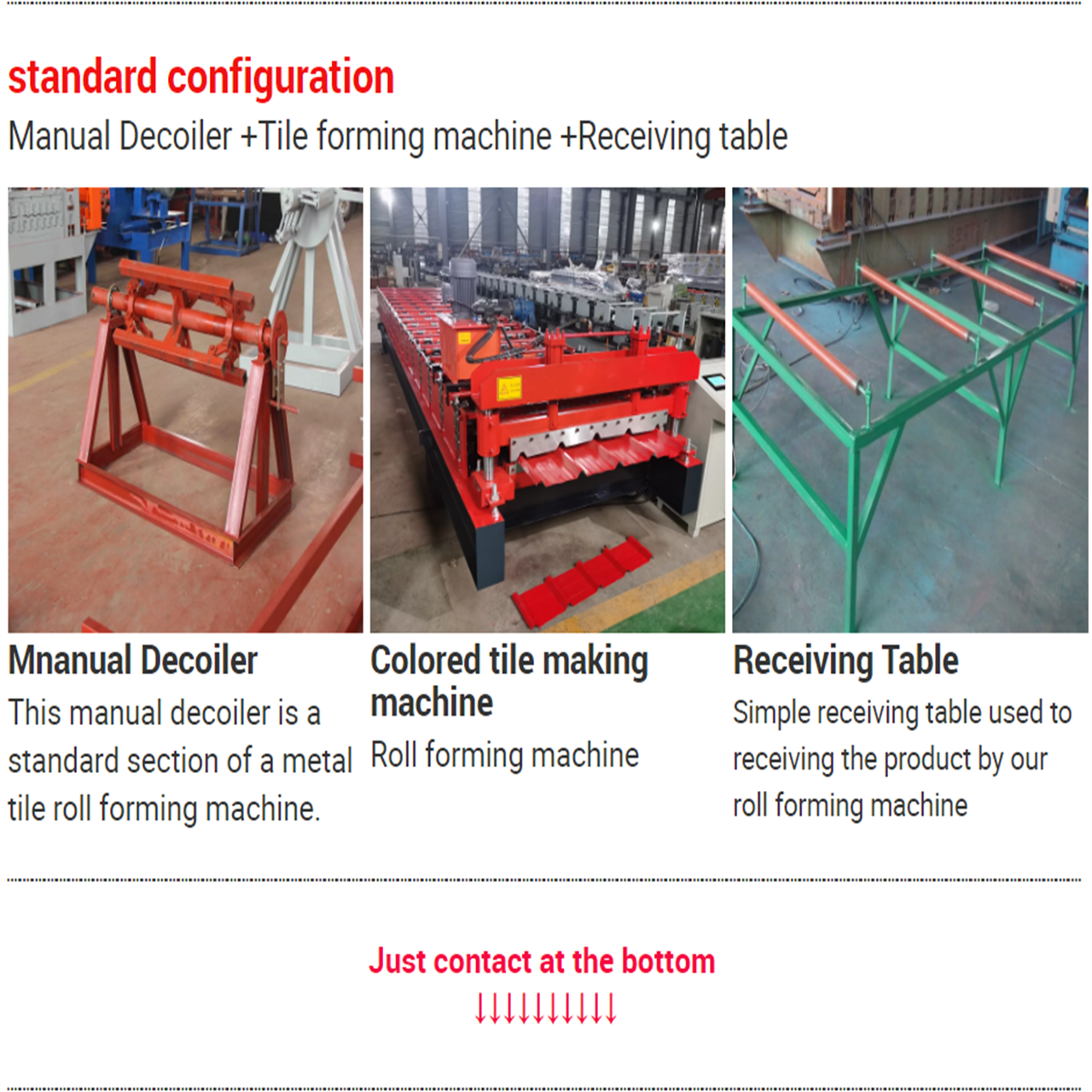
Uncoiling: A heavy coil of sheet metal (often pre-painted, galvanized, or stainless steel) is mounted onto a decoiler and fed continuously into the line.
-
Progressive Forming: The strip passes through a sequence of mating roller stations (known as flower patterns). Each set of rollers gradually bends the metal by a few degrees. By making incremental bends, the process avoids overstressing the material or cracking protective coatings.
-
In-Line Processing (Optional): Pre-punching, post-punching, slitting, or embossing can be integrated directly into the automated line before or after forming.
-
Cutting to Length: Once the final profile is shaped, an automated flying shear or hydraulic cutter cuts the continuous panel into precise custom lengths without interrupting the line speed.
Key Advantages of Metal Roll Forming
-
Continuous High Output: Roll forming lines operate at high speeds (typically 20–50 meters per minute), significantly outperforming press brakes for mass production.
-
Tight Dimensional Tolerances: Advanced PLC automation and precision-machined rollers ensure strict dimensional consistency across every piece produced.
-
Material & Cost Efficiency: Minimizes scrap metal waste and eliminates extra handling steps by integrating punching, bending, and cutting into a single automated line.
-
Design Flexibility & Surface Protection: Capable of producing complex, multi-bend profiles while preserving surface finishes, galvanization, and paint coats.
Common Applications
Metal roll forming is widely used across multiple heavy-duty industries:
| Industry | Common Roll-Formed Products |
| Building & Construction | Trapezoidal roof tiles, standing seam panels, C/Z purlins, drywall studs, rain gutters |
| **Automotive &# What is Metal Roll Forming? |
Metal roll forming is a continuous, high-volume manufacturing process that bends long strips of sheet metal—usually coiled steel or aluminum—into custom cross-sectional profiles.
Unlike traditional press braking or stamping, which processes metal in single discrete batches, roll forming shapes metal incrementally at room temperature (cold forming) through a series of consecutive roller dies.
How Metal Roll Forming Works
The roll forming process relies on a line of paired roller stations that gradually shape the metal in steps:
-
Coil Unloading & Uncoiling: A heavy coil of flat metal strip is loaded onto an uncoiler and fed continuously into the machine.
-
In-Line Pre-Punching: Automatic presses notch, punch holes, or create slots in the flat strip prior to shaping.
-
Progressive Roll Shaping: The strip passes through multiple sets of upper and lower rollers (called roll stations). Each station bends the metal slightly more than the previous one, preventing stress fractures and material strain.
-
Cutting & Shearing: A flying hydraulic shear cuts the finished profile to exact target lengths without stopping the continuous line.
Key Benefits of Roll Forming
-
High Speed & Efficiency: Lines operate at speeds up to 20–50 meters per minute with minimal manual labor required.
-
Consistent Quality & Precision: Heavy-duty tool steel rollers controlled by PLC automation ensure exact tolerances across thousands of identical panels.
-
Material Waste Reduction: Continuous coil processing generates virtually zero scrap compared to conventional sheet stamping or trimming.
-
Complex Profiles: Produces intricate shapes—such as standing seam panels, hat channels, C/Z purlins, and tubular sections—in a single continuous pass.
Common Applications
-
Building & Construction: Roof tiles, wall cladding panels, gutters, structural purlins, and steel framing studs.
-
Automotive: Bumper beams, door impact bars, and chassis structural rails.
-
Solar & Energy: Solar panel mounting racks and support structures.
-
Storage & Industrial: Warehouse racking systems, shelving, and heavy-duty tracks.


