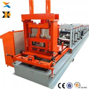

A complete C and Z purlin production line, built and supplied factory-direct — the forming machine together with decoiler, leveling, hydraulic punching, cutting, output handling and control, configured for pre-engineered building fabricators.
This page is written about the line, not the machine alone, because that is the distinction that decides what a buyer actually receives and what they actually pay. A purlin machine is one unit inside a production line. A purlin production line is a system of components that each have to be specified, matched to the material, correctly sequenced, and delivered together — and the single most common way buyers lose money in this category is by comparing total prices without first comparing what is inside each total.
For a pre-engineered building fabricator, the purlin line is not a standalone purchase. It is one line among several feeding the same shop, and its output has to keep pace with the building packages the shop has sold. That is why this page treats it as a system, and why the configuration questions below are framed around throughput and bundle handling rather than around the machine in isolation.
What “production line” actually includes.
A complete purlin production line in this factory’s range is built from a standard set of elements, arranged in the direction the material travels. The sequence runs from the coil entry end to the finished output end, and every configuration in the range uses the same basic order.
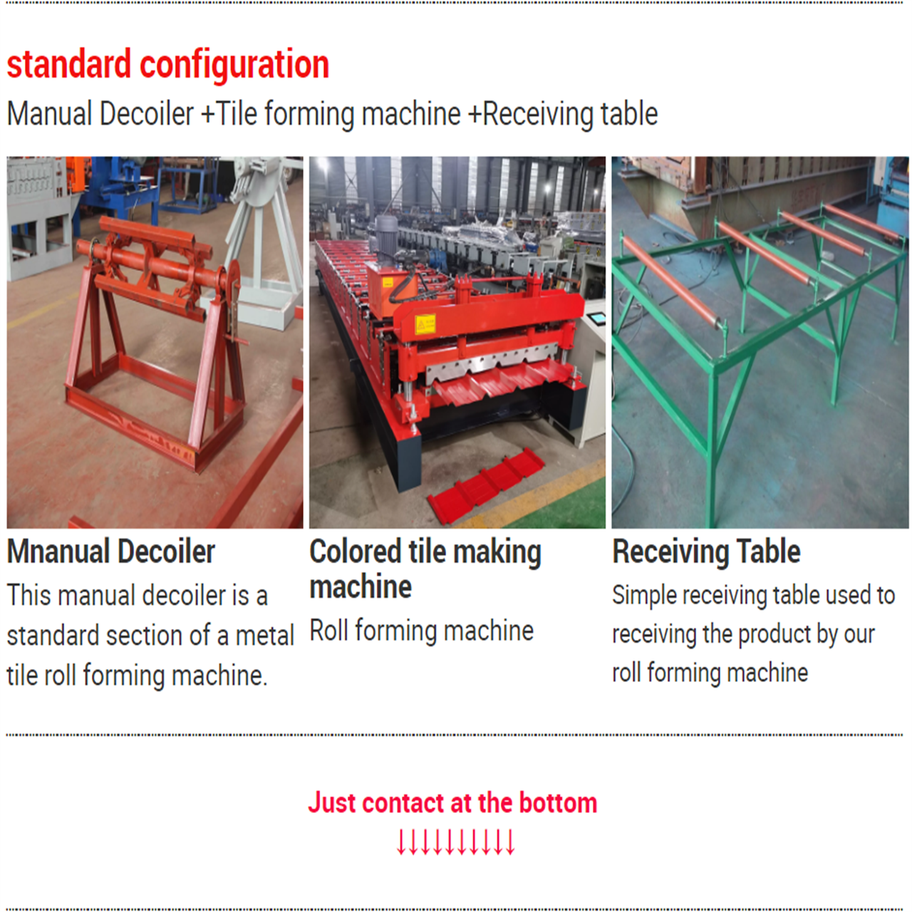
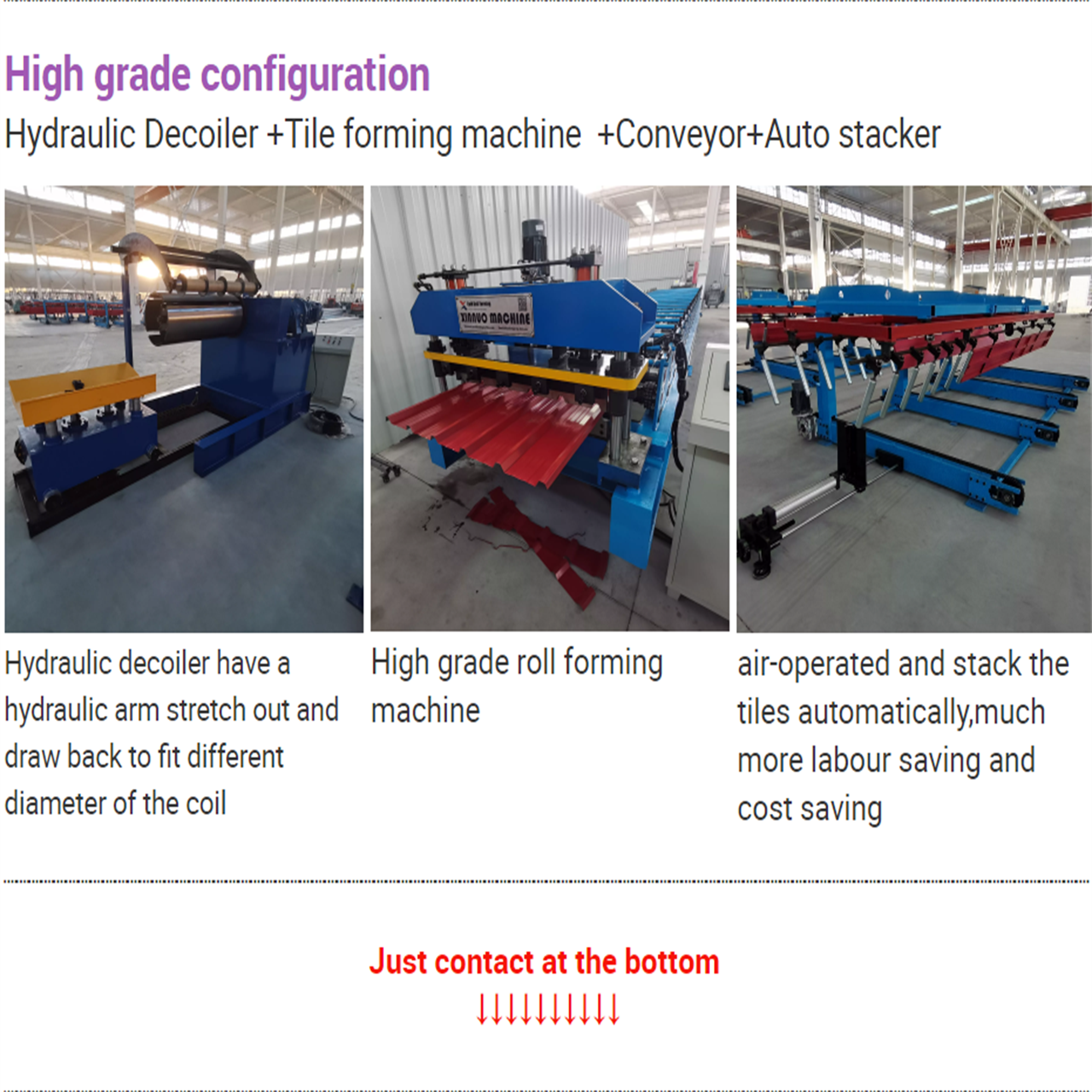
At the entry end sits the decoiler, which carries the steel coil and pays it off into the line. Its type and capacity are a specification choice, not a fixed item, and they must match the coil weights and widths the buyer can actually purchase locally.
Next comes the leveling section, which flattens the strip before it reaches the forming unit. This section appears in every line layout in the archive, and the reason is practical rather than decorative: coil arrives carrying its own set from the mill and from storage, and a purlin formed from strip that was never leveled will not sit flat or cut square.
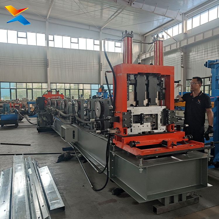
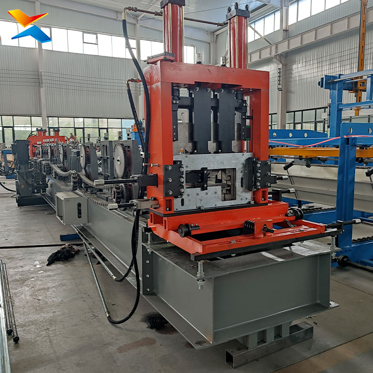
Then the forming unit — the long body of the line, where the strip is progressively brought to the finished C or Z cross-section through its roller stations. This is the component buyers think of when they say “the machine”, and on a full line it is one section of several.
Then punching, performed inline so that the holes your connections require are made as part of the same pass rather than as a separate operation.
Then the cutting arrangement, which separates the finished member to length. This is the single most consequential configuration choice on the line, and it is covered in its own section below.
Then the output handling — the bracket or run-out table that receives the finished, cut members and holds them clear of the line.
And finally the control system and the hydraulic power unit, which drive and coordinate the line. On some configurations the control cabinet is floor-standing beside the forming unit with the hydraulic pump station under or beside it; on others the controls are integrated into the forming section. Which arrangement you are quoted is a scope question, and it is worth confirming.
That list is the answer to the question most worth asking a supplier: what is actually in your total? Two quotations for what look like the same purlin line can differ because one includes leveling and another leaves it out, because one specifies a powered decoiler and another a manual one, because one includes inline punching and another expects the holes to be drilled afterwards, or because one includes a run-out table and the other stops at the shear. Ask for the component list item by item, ask for the layout drawing that goes with it, and compare like with like before you compare prices.
Hydraulic punching — what the term means, and the questions that make it specific.
Punching is the operation that makes the connection holes in the purlin, and it is one of the two reasons a purlin line exists as a line rather than as a forming machine — the members must come off the line ready to bolt, not ready to be taken away and drilled.
The word “hydraulic” refers to how the punching force is applied, and it is worth being precise about what that buys a buyer rather than treating it as a catalogue adjective. A hydraulic punching arrangement applies substantial force in a controlled stroke, which is what allows the punching to be performed on the moving line, inline, without stopping production to load each member into a separate press, and without deforming the section around the hole. On the heavier lines in this range the punching station is positioned ahead of the forming unit, on the entry side, which lets the flat strip be punched before it is formed — an arrangement that suits heavier material and higher punching demands. On the lighter lines the punching station sits after forming. Either arrangement is legitimate; what matters is that the quotation states which one you are getting and why.
Several questions turn “hydraulic punching” from a phrase into a specification, and every one of them should be answered in writing:
Ask whether the punching pattern is built to your connection detail, rather than being a fixed pattern the machine happens to produce. Purlin connection details differ between projects and between fabricators, so the punching tooling is a specification item, and a quotation that does not ask for your pattern has not been configured for your work.
Ask how many holes, in what arrangement, in one stroke — because a pattern requiring multiple positions affects the punching station, the cycle time and the cost.
Ask whether the punching is linked to the counter, so that the final member of a bundle is punched correctly rather than being cut from unpunched stock. On a line running many short bundles, the end of each run is where waste accumulates, so this is a small detail with a real effect on yield.
And ask how the section is supported at the punch, because an unsupported section can be marked or distorted by the punch, and a purlin with a deformed hole face is a connection problem on site rather than in the shop.
The cutting arrangement: the one decision that shapes the whole line.
Of every specification choice on a purlin line, the cutting arrangement changes the most — the length of the line, the throughput, the length accuracy of the finished members, and the price. It is worth understanding before you compare machines, and it is worth asking for as a separate line item.
The standard arrangement is a hydraulic stop-cut shear: the line briefly pauses while the shear separates the finished member to length, then resumes. It is the conventional and economical answer, and it suits normal production volumes and varied cut lengths, where the small pause is absorbed into the working rhythm and the line is not required to run continuously.
The alternative is a non-stop or flying cut, where the shear travels with the moving section and cuts it while the line keeps running, so the line never stops to cut. Two benefits follow, and they are the ones high-volume buyers care about. Output becomes effectively continuous, because no time is spent decelerating and re-accelerating around each cut — the practical difference in sustained output is substantial rather than marginal. And cut length accuracy improves, because the member is not being arrested and released at each cut.
The cost of that is a longer forming unit and a longer line overall, plus a higher price, because the flying mechanism travels with the material and has to be built into the forming section. For a fabricator producing standard purlin sizes in high volume with tight length tolerances — which describes a pre-engineered building shop more often than not — the non-stop arrangement is usually the right answer, and it should be quoted explicitly so that the comparison is made on like terms. For a fabricator producing normal volumes at varied lengths, the standard arrangement is correct and the money is better spent elsewhere.
The stacking option, and why it matters more to a PEB fabricator than to others.
Every purlin line can be bought with an automatic stacking section added after the shear. It counts the finished members, aligns them, and stacks them into bundles ready for handling and transport — replacing the manual labour that otherwise stands at the output end of the line all day catching, counting and stacking members one at a time.
This option deserves particular attention from a pre-engineered building fabricator, for a structural reason rather than a convenience one. A PEB shop ships components to site as identified bundles, and the purlin bundle is one of the things the site crew expects to receive ready to lift. If the purlin line delivers loose members that then have to be counted and bundled elsewhere, the line has simply moved its bottleneck rather than solved it. A stacking section closes that gap at the point where it is cheapest to close, and it is the most automated configuration available in this range.
The trade-offs should be understood rather than glossed. The stacking section adds length to the line, and it is the longest configuration in the range. It also changes the decoiler specification, because the more automated configurations in this range use the higher-capacity tripod or A-frame decoiler rather than the standard cantilever type — a difference worth confirming at order stage rather than discovering later. Whether the stacking section earns its place depends on your labour cost, your bundle discipline, and how consistently the line runs large batches rather than many small ones.
What the line looks like on the floor, and the space question buyers get wrong.
A purlin production line is a long, narrow installation. It runs in a straight strip across the shop floor: coil at one end, forming unit through the middle, cutting at the far end of the forming section, and finished output beyond it. The forming unit is the long body of the line, and around it the entry components and the output handling each take up further length.
The space question buyers get wrong is treating the machine footprint as the space requirement. Three things have to be added to it. The entry end needs room for the decoiler and its coil handling, including the space to load a new coil. The output end needs room for the finished members, which is a moving material requirement for long pieces rather than a fixed one — the output handling can be supplied in a longer version specifically for buyers cutting long members, and this should be decided at order stage because it changes the line length. And the whole line needs clear access along both sides for operators to work at the punch, the shear and the settings, and for maintenance access to the roller stations — clearance that is routinely omitted from a buyer’s floor plan and then found to be missing once the line is installed.
The different configurations in this range are not the same length. A line with the flying cut is longer than the equivalent stop-cut line, because the cutting mechanism is built into the forming unit. A line with the stacking section is longer again. A heavy integrated line with more forming stations is longer than a light one. And the widest machines on the floor are wider as well as longer, because a heavier frame and heavier shafts occupy more depth across the line. All of which is why the correct answer to “how much space do I need” is not a number that can be quoted from a page: it is a layout drawing issued with the quotation, showing the arrangement you are being sold, which the buyer then compares against the actual shop. Any supplier who will not provide that drawing before the order has left the buyer to guess.
A related point that catches buyers who have not bought a coil line before: the line has a working height and a width that must be checked against the building. This is not a machine that can be squeezed under a low roof or threaded through a doorway afterwards. Check the roof structure, the crane rails if the shop has them, the door openings, and the route the line will travel from the delivery point to its final position, before the order is placed.
Two components worth specifying deliberately.
The decoiler is the component most often left to the supplier’s default, and it should not be. The standard cantilever type in this range covers the ordinary coil weights a fabricator buys, while the higher-capacity tripod or A-frame type is used where heavier coils are needed and appears on the more automated configurations. If your coil purchasing habit is to buy heavier coils at better prices — which is common in markets where coil has to be imported in quantity — say so at the enquiry stage, because the decoiler has to match your purchasing pattern, not a nominal figure on a specification sheet. The decoiler also sets the line’s footprint at the entry end, so it belongs in the layout drawing.
The output handling is the second. The standard arrangement is a pair of brackets that receive the cut members. For buyers cutting members of considerable length, the brackets can be supplied in a longer version, and this should be decided with the order because it changes the line length and the floor plan. A line that cuts long members into undersized output brackets forces the operators to drag them off unsupported, which is both a handling problem and a risk to the straightness of the finished member.
Why a pre-engineered building fabricator is a different kind of buyer.
The term PEB refers to the pre-engineered building — a building designed as a package, with the steel structure and its secondary framing fabricated in a factory to a fixed design and then assembled on site. It is a systemised approach to construction, and it puts a fabricator into a different operating pattern from a shop that does general steelwork: a PEB shop runs a catalogue of standard sections at volume, in identifiable bundles, against a delivery schedule, and its profitability rests on throughput, repetition and the elimination of manual handling rather than on bespoke work.
That operating pattern changes what the right purlin line looks like, in four ways that are worth setting out plainly.
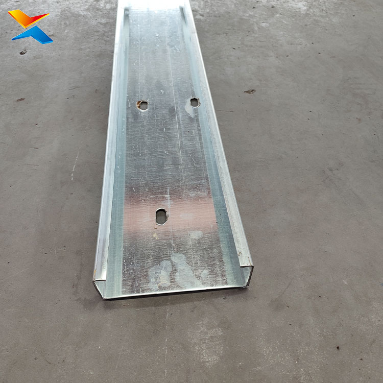
First, the section mix. A PEB package does not use one purlin section. Its design typically calls for Z sections in the roof purlin positions, because of the lapping advantage that lets Z members work as continuous runs, and C sections in the wall girt and other positions. A PEB fabricator therefore needs both C and Z purlins routinely, as a matter of course and in the same production plan — which is exactly why this title pairs a purlin production line with a C/Z channel-making machine. If your packages use both, you are not choosing between a C line and a Z line; you are choosing between two dedicated lines and one line that does both. The integrated C/Z machines in this range exist precisely for that buyer, and the decision between one integrated line and two dedicated lines should be settled with the supplier against your own order book rather than on principle.
Second, volume and repetition. PEB work rewards a line that runs the same sizes at volume, which shifts the configuration argument toward the non-stop cutting arrangement, and rewards quick and repeatable size change, because a PEB shop changes between standard sizes rather than producing one size forever. The adjustability that looks like an unnecessary cost to a single-size fabricator is what makes a PEB line efficient.
Third, bundle discipline. As set out above, PEB components leave the shop as identified bundles for the site crew. The stacking section is the configuration that keeps that discipline at the purlin line rather than pushing it downstream.
Fourth, line integration. The purlin line is one of several lines in a PEB shop — alongside the roof and wall panel line, and often a decking or accessory line — and it has to keep pace with the packages the shop has sold. A purlin line specified in isolation, on its own throughput, will become the constraint in the shop if the other lines outrun it. Buyers should quote the line against the shop’s required output per shift for purlins specifically, rather than against a general impression of what a purlin machine does.
One clarification that belongs with the term PEB.
Because PEB is used loosely in enquiries, and because the sections involved overlap in name, it is worth saying plainly what this line makes and what it does not. This is a cold roll forming line for C and Z purlin sections — the secondary framing of a steel building, formed from coated steel coil, with punching and cutting performed inline. It is not a line for the primary structural members of a PEB frame, which are welded plate girders and columns, a different fabrication process entirely. It is also not a U channel line: a U section has no lips where a C section does, and while integrated machines exist that cover C and U on one body, that is a different configuration from the C/Z integrated machine described here and should be specified deliberately if it is what you need. Buyers who send a drawing and an application rather than a name get the right machine; buyers who order from a name get the surface appearance of the right machine.
The Middle East market, and one honest limitation of the record.
The region’s construction market suits this line well. PEB and systemised steel building work covers the industrial, logistics, warehousing, cold storage and factory building types that dominate Gulf construction programmes, and these are exactly the buildings whose secondary framing is purlin sections produced in volume to a repeated design. The scale at which such projects are let in the Gulf means the fabricator serving them is running standard sections continuously rather than making one-off members, which is the operating pattern a properly configured purlin line is built for.
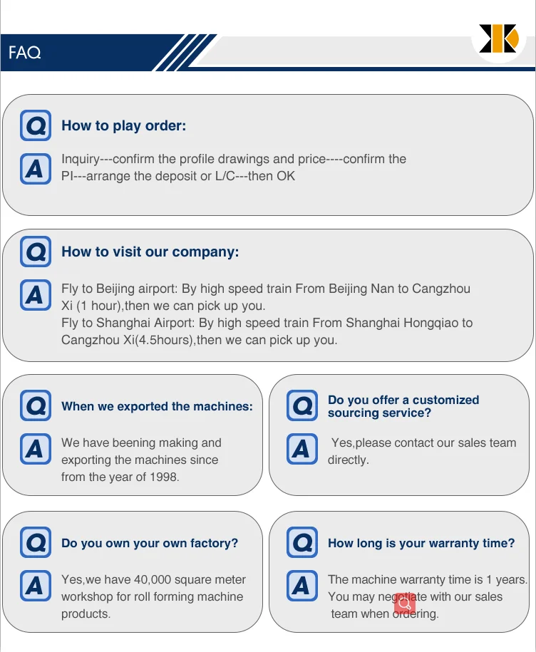
This factory’s documented purlin deliveries in the region include the United Arab Emirates — Dubai specifically — along with Saudi Arabia, Oman and Yemen, with further deliveries to Israel and Turkey. That record is documented for the purlin machine range, and a buyer should ask for the specifics relevant to their own profile and line configuration rather than accepting a general regional claim. Where a requirement falls outside the documented range — a special cross-section, an unusual material, or a line configuration not previously built — the honest answer is that the tooling or the configuration would be new, and that should be stated in writing before the order rather than discovered during commissioning.
♦ COMPANY PROFILE:
Hebei Xinnuo Roll Forming Machine Co., Ltd., not only produce different types of professional roll forming machines, but also develop intelligent automatic roll forming production lines, C&Z shape purline machines, highway guardrail roll forming machine lines, sandwich panel production lines, decking forming machines, light keel machines, shutter slat door forming machines, downpipe machines, gutter machines, etc.
Advantages of Roll Forming A Metal Part
There are several advantages of using roll forming for your projects:
- The roll forming process allows operations such as punching, notching, and welding to be performed in-line. Labor cost and time for secondary operations are reduced or eliminated, reducing part costs.
- Roll form tooling allows for a high degree of flexibility. A single set of roll form tools will make almost any length of the same cross-section. Multiple sets of tools for varying length parts are not required.
- It can provide better dimensional control than other competing metal forming processes.
- Repeatability is inherent in the process, allowing easier assembly of roll formed parts into your finished product, and minimizing problems due to “standard” tolerance build up.
- Roll forming is typically a higher speed process.
- Roll forming offers customers a superior surface finish. This makes roll forming an excellent option for decorative stainless steel parts or for parts requiring a finish such as anodizing or powder coating. Also, texture or pattern can be rolled into the surface during forming.
- Roll forming utilizes material more efficiently than other competing processes.
- Roll formed shapes can be developed with thinner walls than competing processes
Roll forming is a continuous process which converts sheet metal into an engineered shape using consecutive sets of mated rolls, each of which makes only incremental changes in the form. The sum of these small changes in form is a complex profile.