

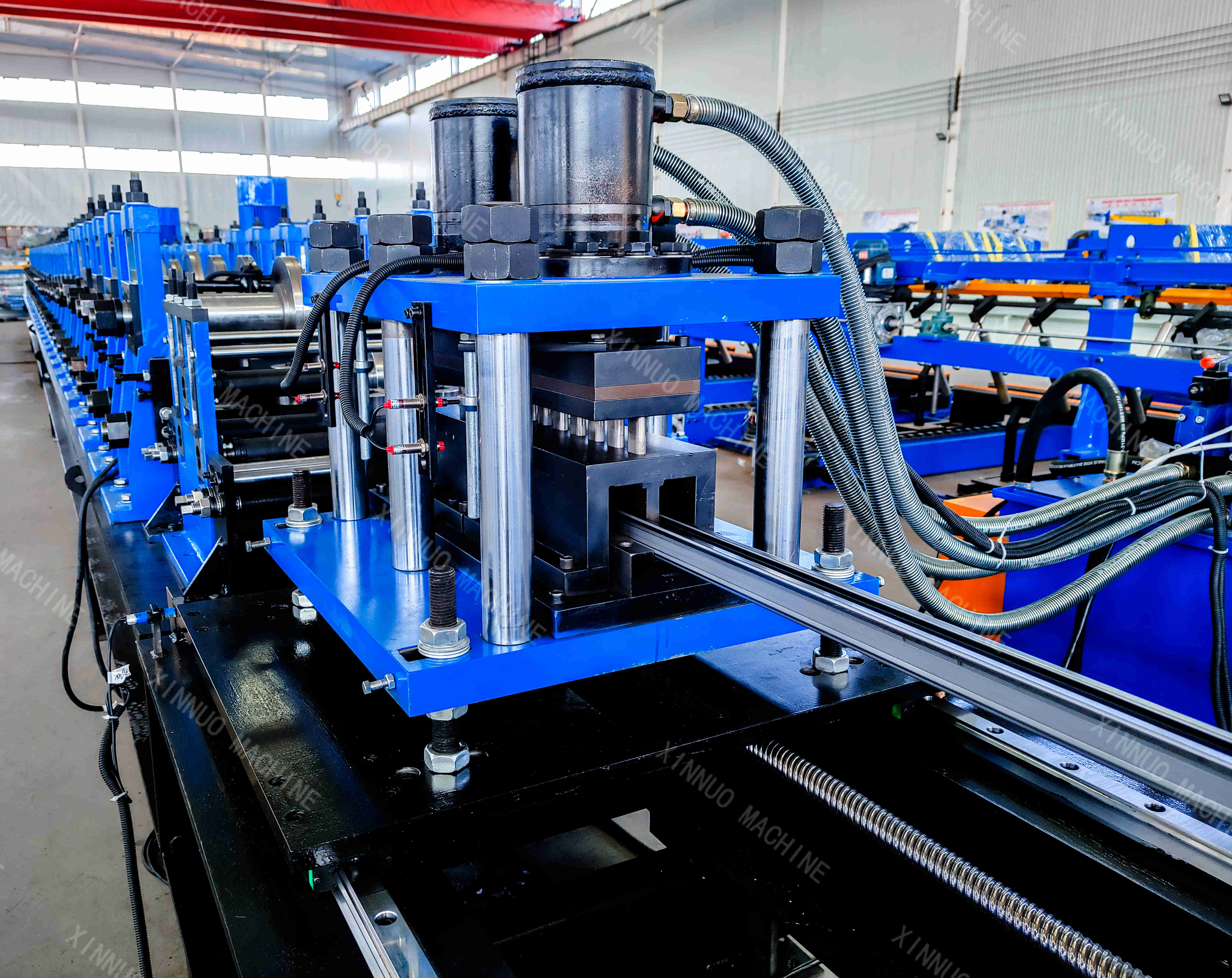
Hebei Xinnuo has developed solar bracket roll forming lines for manufacturers that produce mounting rails, bracket columns, cross beams, and other support profiles for photovoltaic projects. A typical line combines coil feeding, leveling, roll forming, in-line punching, cut-to-length, and finished-profile collection.
The steel strip enters the line from a decoiler and is leveled before passing through the forming rollers. When the project requires it, servo-tracking punching and a servo-tracking flying saw are added after the forming section. This allows the profile to be punched and cut while it is moving through the line, reducing the need for a separate drilling and cutting operation.
The equipment is designed from the actual profile drawing. Material grade, thickness, hole layout, profile height, product length, and workshop space all affect the final design. For this reason, a solar bracket machine is not supplied as one fixed standard model.
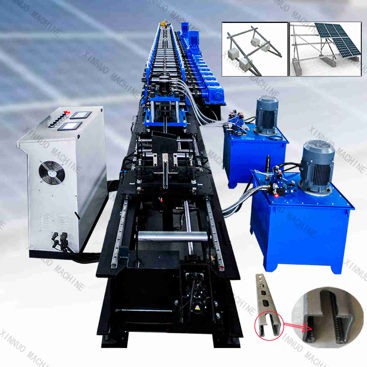
Production Process from Steel Coil to Finished Profile
The line follows a straightforward sequence:
- A steel coil is placed on the decoiler.
- Entry guides and feed shafts direct the strip into the line.
- Leveling shafts reduce material deviation before forming.
- Forming rollers gradually create the required bracket cross-section.
- The servo-tracking punching unit makes the specified holes.
- The servo-tracking flying saw cuts the formed profile to the required length.
- The run-out table receives the finished sections for collection and packaging.
The punching arrangement can be designed for continuous holes, holes at both ends, or no holes. Replaceable punching dies may be used when a project requires more than one hole pattern.
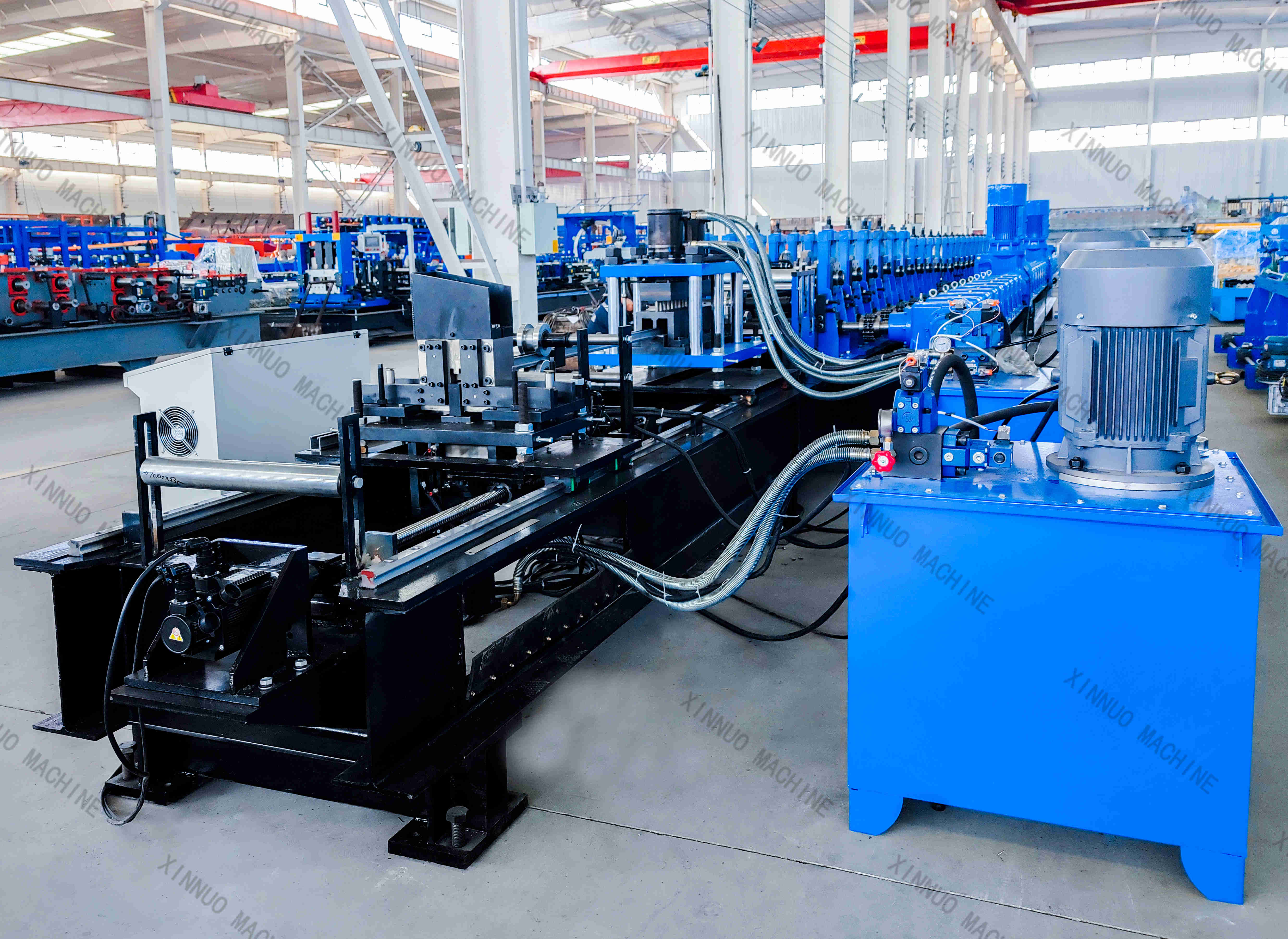
Reference configuration from completed project records
The following table shows a reference configuration from archived solar bracket equipment projects. It is not a universal specification for every solar bracket roll forming machine.
| Parameter | Reference configuration |
|---|---|
| Typical materials | Q195, Q235, A36 and other steels; final material must be confirmed |
| Material thickness | 1.5–2.5 mm in the reference projects |
| Forming section | 25 forming stations plus 12 auxiliary adjustment stations |
| Main shafts | 45# steel, approximately 80 mm diameter |
| Main frame | 450 mm H-beam steel |
| Main drive | 2 × 15 kW motors with 2-inch chain transmission |
| Leveling section | 7 leveling shafts: 3 upper and 4 lower; approximately 80 mm shaft diameter |
| Feed section | 2 feed shafts, approximately 100 mm diameter |
| Punching | Servo-tracking punching; hole pattern designed from the profile drawing |
| Cutting | Servo-tracking flying saw; stop-cut can be added for short sections when required |
| Reference line speed | Approximately 15 m/min with punching and cutting; forming-only speed in one reference project reached 18 m/min |
| Reference cutting tolerance | ±1 mm; final value depends on the acceptance plan |
| Control | PLC, touch screen, and encoder-based control system |
| Run-out table | 6 m or 9 m, depending on the line layout |
| Power supply | Some reference projects use 380 V, 50 Hz, three-phase power; destination requirements must be confirmed |
The reference projects also include configurations with a manual decoiler, a 5-ton decoiler, servo-tracking punching, a servo-tracking saw, a PLC control cabinet, and a 6 m or 9 m run-out table. The exact equipment list depends on the project design.
In-Line Punching for Solar Mounting Profiles
Solar mounting profiles often require holes for bolts, clamps, connectors, or installation accessories. If the profile is formed first and drilled later, the manufacturer must handle and position the long section again.
In-line servo-tracking punching performs the hole-making step while the strip continues moving. The control system uses encoder feedback and the programmed hole layout to coordinate the punching position with the moving material.
The final hole position depends on several factors:
- Steel grade and thickness;
- Material flatness and entry alignment;
- Profile shape and stiffening ribs;
- Hole diameter and hole spacing;
- Number of holes per section;
- Punching die design;
- Machine adjustment and commissioning.
A servo motor by itself does not guarantee a specific hole-position result. The machine should be tested with the material and profile required for the customer’s project before regular production.
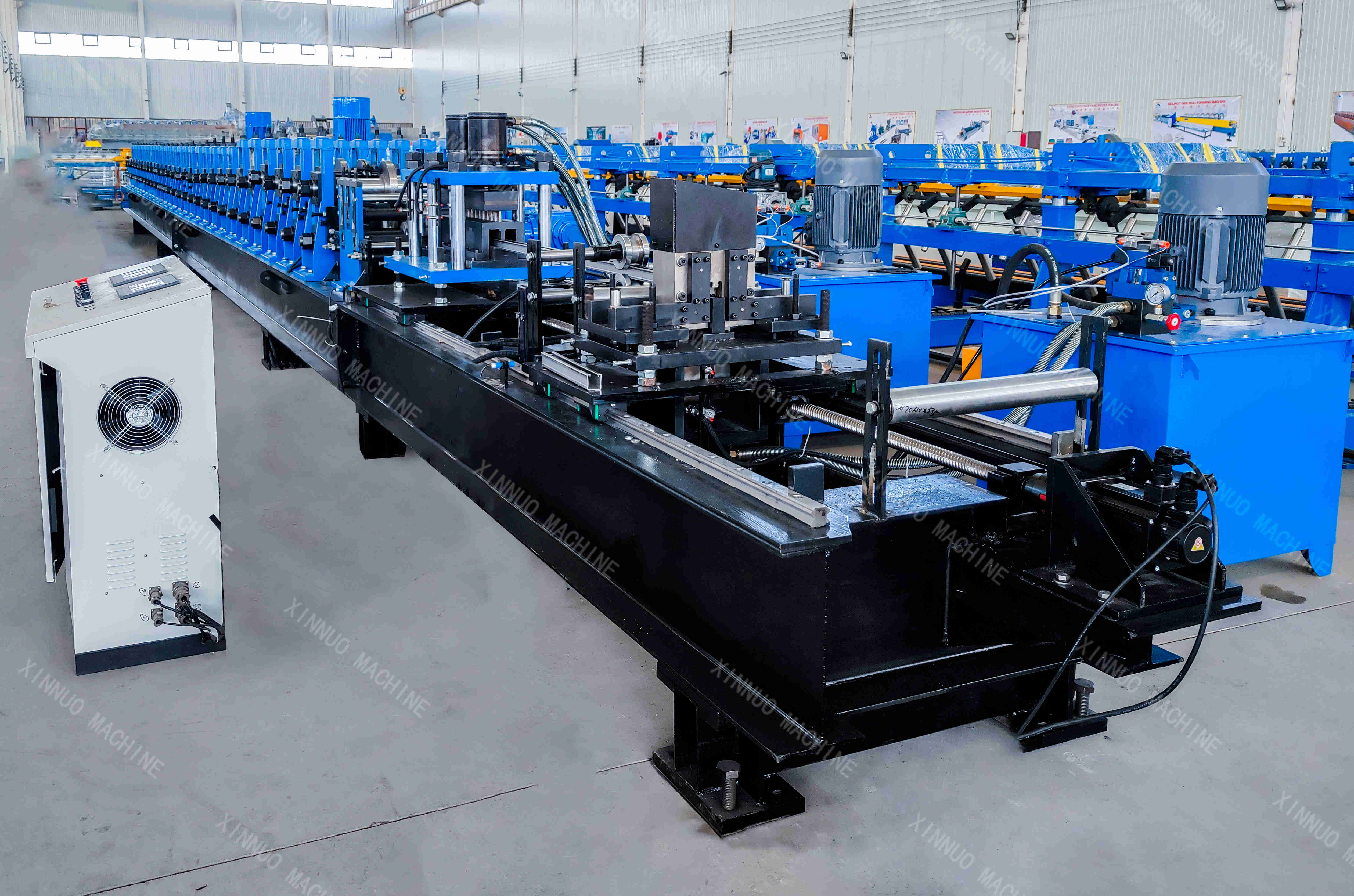
Servo-Tracking Flying Saw for Different Bracket Lengths
Solar bracket sections may have different lengths depending on the installation position. A servo-tracking flying saw cuts the formed profile while it is moving through the line. This can reduce repeated stops when the cutting length and production conditions allow continuous cutting.
The reference projects include a cutting tolerance of ±1 mm for the servo flying-saw configuration. For very short sections, a stop-cut system may be added. The shortest practical length depends on the profile height, material thickness, hole layout, saw design, and machine speed.
The cutting figure in this article is a reference value. The final cutting tolerance must be stated in the technical agreement and verified during acceptance testing.
Solar Profiles and Typical Applications
The machine can be designed for different solar mounting profiles, including slotted sections with or without stiffening ribs. Typical products include:
- Solar module mounting rails;
- Solar bracket columns;
- Solar bracket cross beams;
- Rooftop PV support profiles;
- Ground-mounted solar support profiles;
- Mounting profiles for commercial and industrial rooftop projects;
- Other cold-formed thin-wall profiles that require punching and cut-to-length.
One machine may produce several similar profiles after the rollers, spacers, guides, or punching dies are changed. Profiles with substantially different sections may require a new roller design or a separate forming machine.
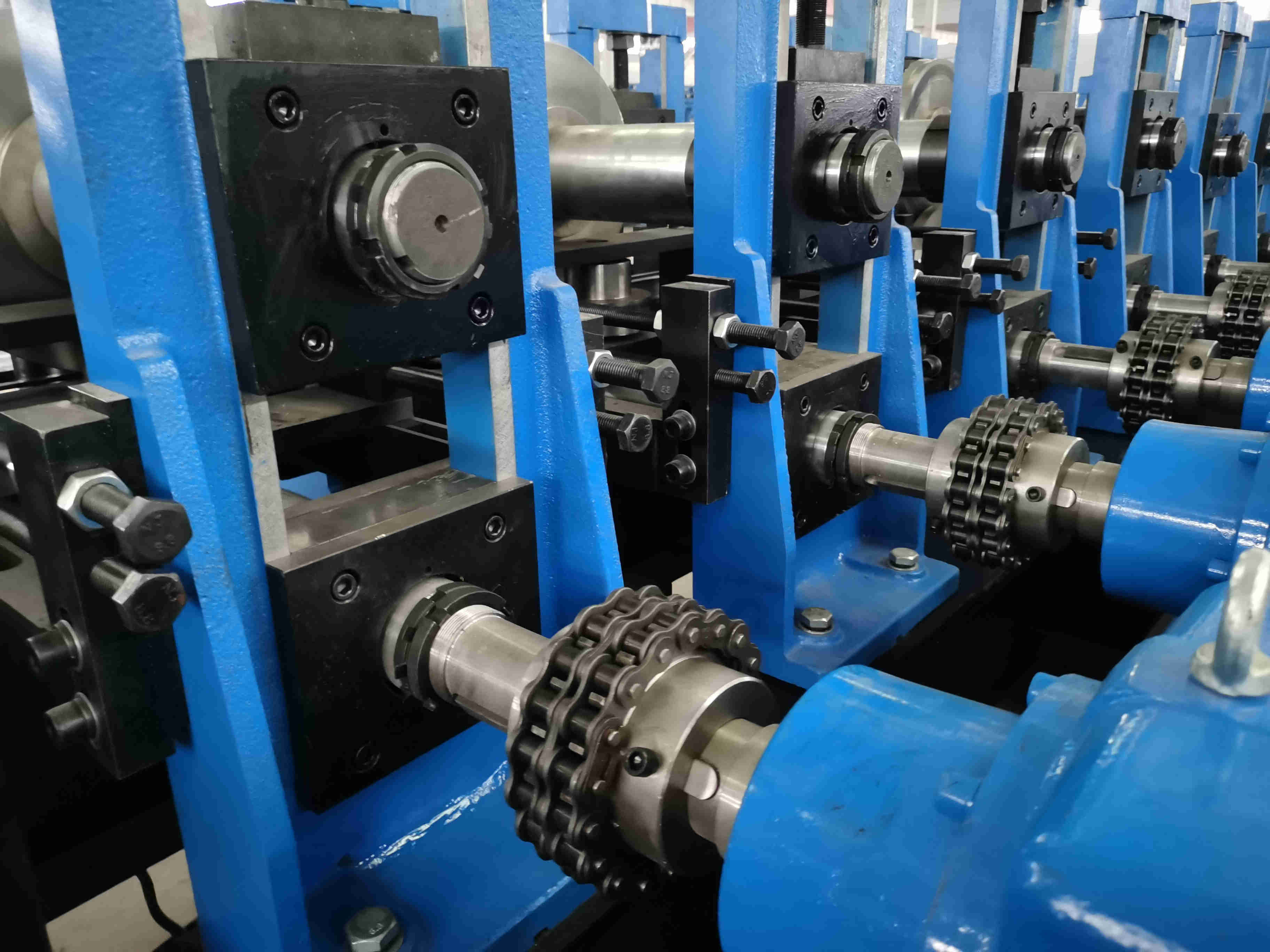
Workshop layout and limited-width installations
A solar bracket production line needs space for more than the main forming machine. The layout should include the coil-loading area, operator access, electrical cabinet, maintenance space, lifting area, finished-profile table, and finished-product storage.
For projects with limited workshop width, the drive-motor position, hydraulic-tank position, and operating area can be reviewed during design. Some reference projects use vertical drive motors and place the hydraulic tank above the machine to reduce side clearance.
Customers requesting a layout proposal should provide:
- Workshop length and width;
- Coil-loading direction;
- Entry and exit positions;
- Lifting equipment and lifting height;
- Electrical connection location;
- Finished-product storage position;
- Required maintenance and operator clearance.
A machine layout should be confirmed from the complete production flow, not only from the length of the forming host.
Information Required for Machine Design
The following documents help the manufacturer prepare a suitable solar bracket roll forming machine proposal:
- Profile cross-section drawing with dimensions and tolerances;
- Steel grade, yield strength, and thickness range;
- Product length range and permitted length tolerance;
- Hole diameter, spacing, pattern, and position;
- Whether the product requires continuous punching, end punching, or no punching;
- Required production quantity and working hours per day;
- Workshop dimensions and lifting conditions;
- Local voltage, frequency, and phase requirements;
- Whether one line must produce several similar profiles;
- Packaging, shipping, and corrosion-protection requirements.
These details determine the roller design, number of forming stations, punching die, cutting system, drive arrangement, control program, and run-out-table length.
Frequently Asked Questions
What is a solar bracket roll forming machine?
It is a cold roll forming line that converts steel coil into solar mounting brackets and support profiles. Depending on the project, the line can also include leveling, in-line punching, cut-to-length, and finished-profile collection.
Can the machine punch holes without stopping?
Yes. A servo-tracking punching unit can punch the moving strip without using a stop-and-punch cycle. The exact hole pattern and position must be designed from the customer’s profile and installation requirements.
Can one machine make different solar bracket sizes?
It can make several similar sizes when the forming range, rollers, spacers, guides, and dies are suitable. A profile check is required before confirming multi-size production.
What steel thickness can the machine process?
The archived reference projects cover 1.5–2.5 mm material. The actual working range depends on the steel grade, yield strength, profile section, stiffening ribs, and forming design.
What is the reference speed?
One reference configuration runs at approximately 15 m/min with punching and cutting. The forming-only reference speed reaches 18 m/min. Actual speed depends on the hole pattern, cutting length, material, and acceptance requirements.
What is the cutting tolerance?
The reference servo flying-saw configuration has a cutting tolerance of ±1 mm. This value is not automatically applicable to every profile and must be confirmed through the technical agreement and acceptance test.
Post time: Nov-04-2026